electronics
How to Assemble and Set Up Your S.T.A.R.E. Animated Eyes Kit
This guide takes you from the parts in the box to a working pair of animated eyes, then shows you how to fit the optional stand and open the control panel.
The software is already installed, and no soldering is required. You just need to connect the ESP32, both eye displays and USB power.
- Before you start
- 1. Fit the ESP32
- 2. Connect the two eyes
- 3. Plug in the power
- 4. Fit the optional Display Stand & Eye Mount
- 5. Open the control panel
- 6. Connect S.T.A.R.E. to your home Wi-Fi
- 7. Choose an eye, or create your own
Before you start
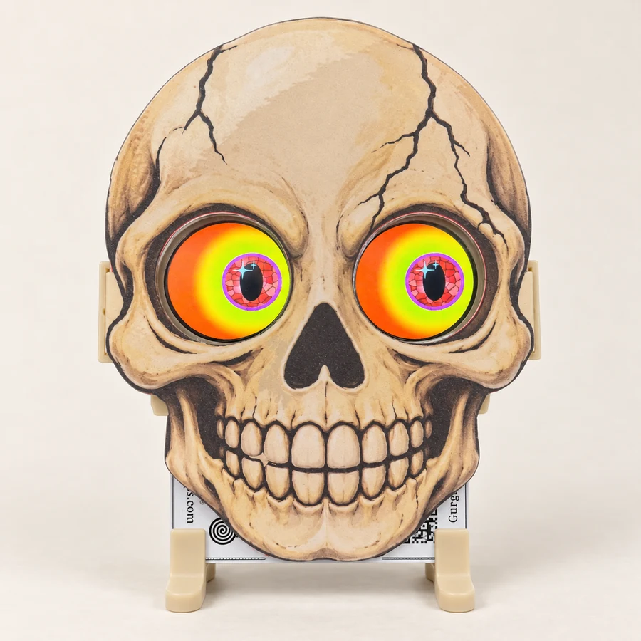
Your Electronics Kit contains a S.T.A.R.E. circuit board, an ESP32, two eye displays, two 7-pin Dupont leads and a Micro USB cable. If you chose the Display Stand option, you will also have two support feet and the glasses-style eye mount.
Work with the USB power disconnected while fitting or changing any connections.
Cable colours can vary between kits. We use the leads available to us, so yours may look different from the photos. Some leads may even have seven wires of the same colour. Follow the printed pin labels and trace the same wire between the two ends; do not copy the colours in these pictures.
1. Fit the ESP32
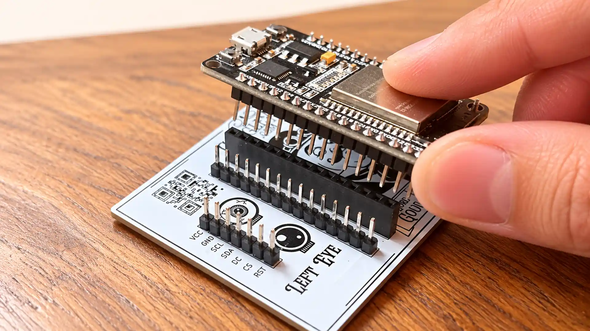
Place the S.T.A.R.E. board with its connectors facing upwards. The ESP32 fits into the two long central sockets, with its Micro USB port towards the top edge of the board.
Line up both rows of pins with the sockets before pressing it in. Check that no pin has missed a socket or shifted along by one position, then press evenly on the board until it is seated.
2. Connect the two eyes
The S.T.A.R.E. board has two 7-pin eye connections marked LEFT EYE and RIGHT EYE. Either display can be connected to either connection: the displays themselves are interchangeable.
Once connected, keep track of which one is plugged into LEFT EYE and which is plugged into RIGHT EYE, so you can put them in the correct positions in your character or model.
Each lead has a seven-position connector at both ends. One end goes over all seven pins on the S.T.A.R.E. board; the other goes over all seven pins on the back of an eye display.
The important check: VCC to VCC
Both boards have a pin marked VCC. The wire connected to VCC on the S.T.A.R.E. board must be the same wire connected to VCC on the eye display.
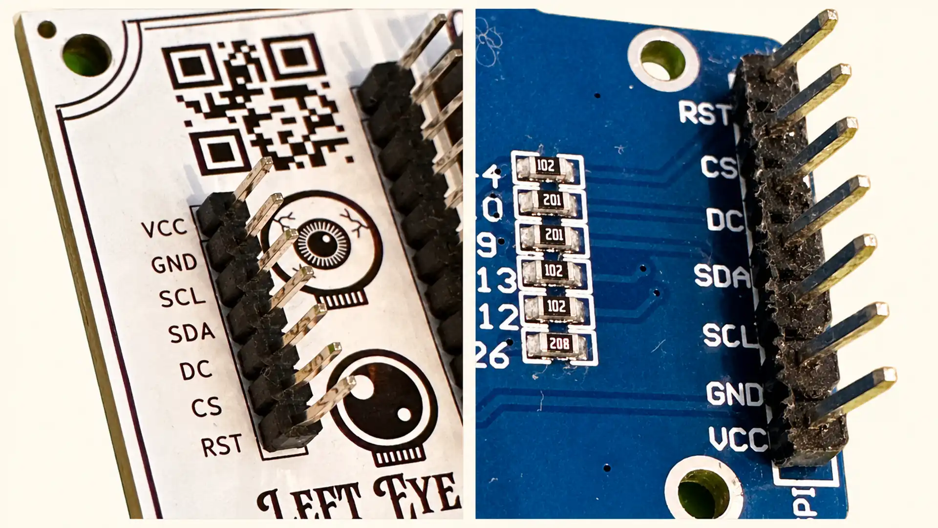
- Find the VCC label beside the eye connection on the S.T.A.R.E. board.
- Fit one connector over all seven pins.
- Identify the wire in the connector position covering VCC.
- Follow that wire to the other end of the lead.
- Fit the eye connector so that this same wire covers the eye display's VCC pin.
Check that both connectors cover the full seven-pin row, with no spare pin sticking out at either end. The remaining labels should also match: GND, SCL, SDA, DC, CS and RST.
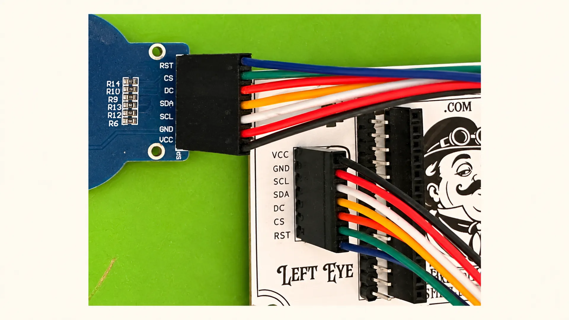
Repeat for the second display. Hold the connector housing while fitting it, rather than pulling or pushing on the wires.
3. Plug in the power
Plug the supplied Micro USB cable into the ESP32, then connect the USB end to a suitable 5 V USB power source. This can be a USB wall adapter, a computer USB port or a power bank.
The displays should light up. You may first see the welcome and network information before the animated eyes appear.
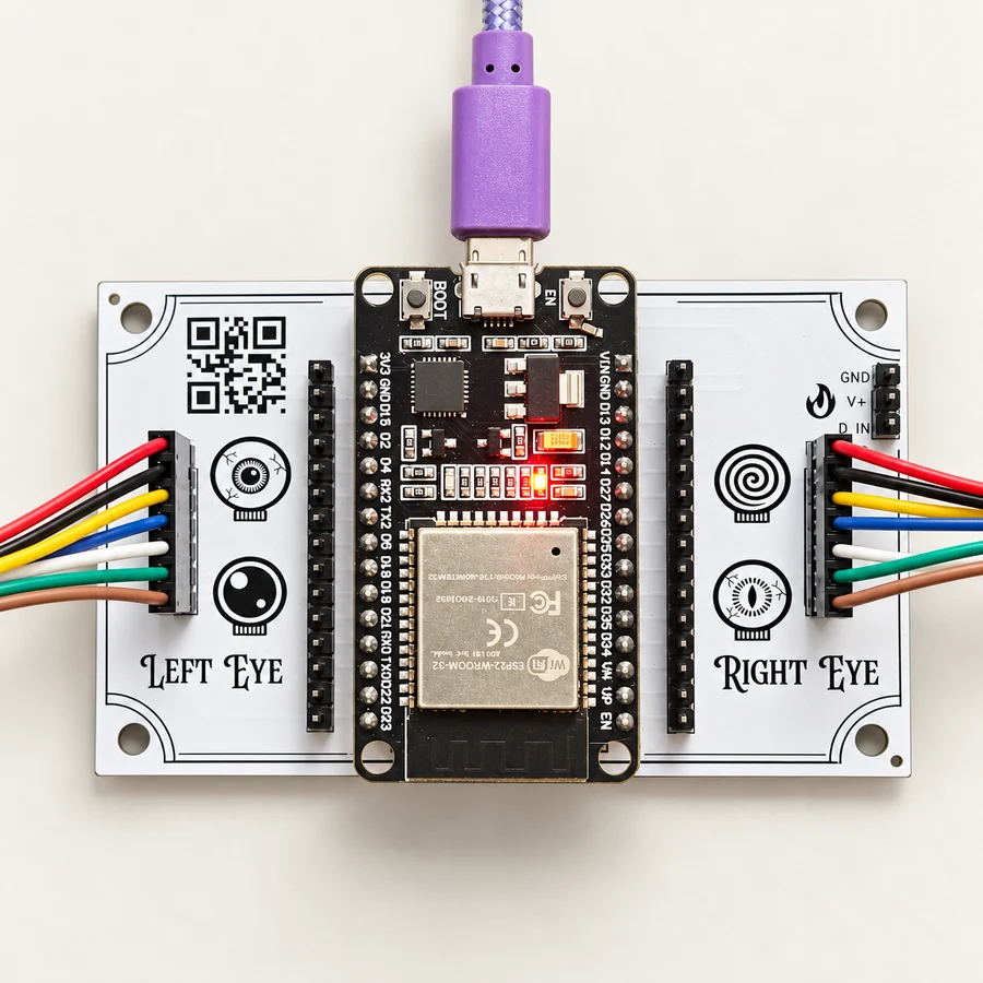
If an eye stays dark
Disconnect USB power first. A reversed connector is one possible cause, so check the lead orientation using VCC to VCC again. If an end is backwards, remove it and turn that connector around before reconnecting power.
Also check that the connector covers all seven pins and the ESP32 is seated correctly. If neither display lights up, try another USB power source and cable.
Do not keep reversing connectors while the kit is powered. If the connections are correct and it still does not work, contact us for help.
4. Fit the optional Display Stand & Eye Mount
If you are using the eyes in your own pumpkin, prop or model, you can skip this section.
Disconnect power before handling the mounting parts.
Slide on the feet
Turn the board so the decorative artwork on its back faces you. Slide the two feet onto the bottom edge of the board, one towards each side.
The short end of each foot faces you, and the long end extends behind the board. With both feet fitted, the board should stand with a slight backwards lean.
Fit the displays into the glasses
Insert each eye display into its seat from the back of the glasses-style frame. Keep the display connected to LEFT EYE in the intended left-eye position and the display connected to RIGHT EYE in the intended right-eye position.
Support the display by its circuit board and edges. Do not press on the screen glass. If it catches, take it out and check its alignment rather than forcing it.
Slide the frame onto the top of the S.T.A.R.E. board. It is a snug fit: align the mounting slots with the board and press gently and evenly. Keep the wires clear of the mounting slots.
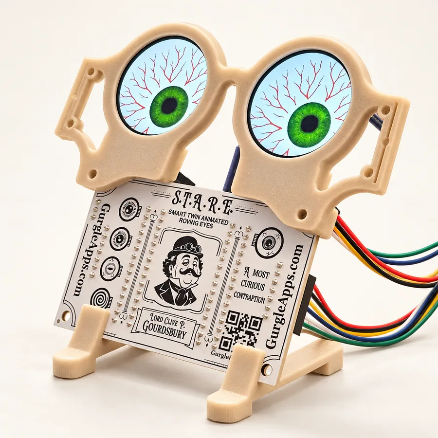
Add a laminated face
Cut the face and side tabs out around their black outlines, then fold the tabs back along the dotted lines. We have already cut the paper out of the eye openings before laminating your sheet, so you don't have to worry about cutting out circular eye holes.
Slide the folded tabs into the slots on either side of the glasses frame, keeping the face's eye openings aligned with the displays.
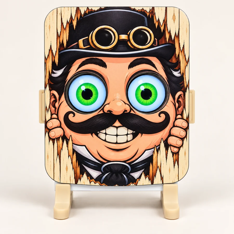
Browse the interchangeable character faces.
5. Open the control panel
You can leave the eyes running without connecting a phone. To choose designs and customise them, open the browser control panel.
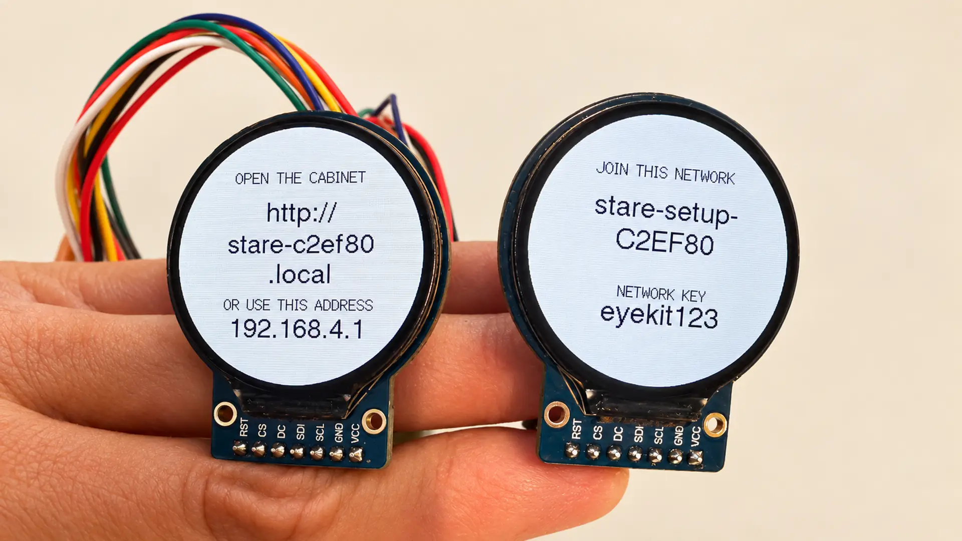
On first setup, the displays show the connection details for your unit. Make a note of the setup Wi-Fi name, password and browser address shown there.
The setup network starts with stare and has a unique ending, so you can tell units apart if you have more than one. For example, a unit might use:
- Setup Wi-Fi:
stare-setup-A88D64 - Browser address:
http://stare-a88d64.local
These are examples. Use the details shown on your own displays.
- Open Wi-Fi settings on your phone or computer.
- Join the S.T.A.R.E. setup network and enter its password.
- If your device warns that this network has no internet, stay connected. This is a direct connection to the eyes.
- Open a browser and enter the displayed address, including
http://.
If the .local address does not open, try http://192.168.4.1/ while still connected to the S.T.A.R.E. setup network. Enter it in the address bar rather than a search box.
6. Connect S.T.A.R.E. to your home Wi-Fi
Before exploring the Workshop, connect the eyes to your home Wi-Fi so you can reach them from your usual network.
- Open the Device tab and find the household Wi-Fi settings.
- Set Household Wi-Fi to On.
- Enter your home Wi-Fi name under Network name, or press Scan and select it from Visible networks.
- Enter your Wi-Fi password under Network password.
- Under Local address, keep the existing name or choose your own. Entering
staregives you the browser addresshttp://stare.local. - Press Save Household Wi-Fi.
- Wait for the status bar to report Local Wi-Fi connected, followed by an IP address. Saving the settings alone does not confirm a successful connection.
- Switch your phone or computer back to the same home Wi-Fi network, then open the browser address shown beneath Local address.
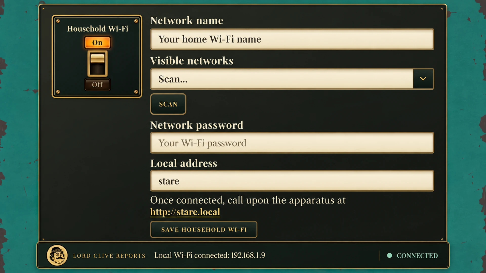
If the .local address does not open, use the IP address reported by your device, with http:// in front. The image shows an example; your IP address may differ. Keep the S.T.A.R.E. setup network enabled until you have confirmed the home Wi-Fi connection works.
7. Choose an eye, or create your own
Start with the supplied eye designs in Eyes / The Collection. Choose one to display, or explore the Workshop to create a character of your own.
The Workshop lets you choose iris patterns, adjust colours and size, change pupil shapes and set movement. Use Try on Apparatus to see your working design on the physical displays, then save the finished eye to your Collection.
You are ready to bring your creation to life. If you want to connect the eyes to your own code or electronic project, explore the API section of the control panel.